Tuesday, February 19, 2013

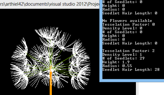
Dandelions - Results

I'll probably continue to work on this (most likely) after this course. But in the scope of this course, this project is done, built, submitted. Done. Finished. A long report has been written and submitted. Its over.

There's a lot of things I'd love to do with it later, but I thought I'd post some images of how it looks these days.

One Dandelion with attributes listed 

A similar dandelion, with different attributes
A lit field. Looks wonky.


Field, with details

Saturday, February 16, 2013

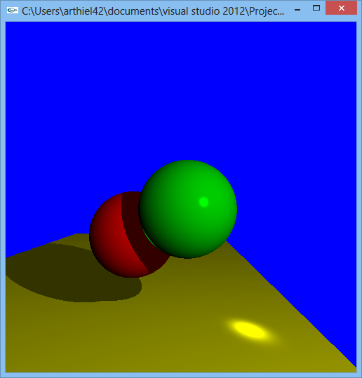
Ray Tracer Part 7 - Tone Reproduction

For the final part of the Ray Tracer, Tone Reproduction, using Reinhard and Ward Compression techniques, were implemented.

Ward Compression

Ward, 1 nit
Ward, 10 nits


Ward, 100 nits
Ward, 1000 nits


Reinhard Compression

This portion I've had a lot of issues with. I realize that in Reinhard, the Max Luminance is supposed to have very little (if any) effect on the luminance of the scene.  Unfortunately, I can't find where in my code this seems to go wrong. The equations seem almost identical to me, and I'm simply at a loss. Instead, I got these interesting images.

My code was as follows (per pixel):
// Part A of Compression            
pixels[y][x].l_red = ( kv * pixels[y][x].l_red ) / log_avg_lum;            
pixels[y][x].l_green = ( kv * pixels[y][x].l_green ) / log_avg_lum;            
pixels[y][x].l_blue = ( kv * pixels[y][x].l_blue ) / log_avg_lum;    
       
// Part B of Compression            
pixels[y][x].l_red = ((pixels[y][x].l_red)/ (1 + pixels[y][x].l_red)) *ld_max; pixels[y][x].l_green = ((pixels[y][x].l_green)/ (1 + pixels[y][x].l_green)) * ld_max;            
pixels[y][x].l_blue = ((pixels[y][x].l_blue)/ (1 + pixels[y][x].l_blue))*ld_max;

// Apply Device Model            
pixels[y][x].l_red = pixels[y][x].l_red / ld_max;            
pixels[y][x].l_green = pixels[y][x].l_green / ld_max;            
pixels[y][x].l_blue = pixels[y][x].l_blue / ld_max;            

// Print Point to Screen            
glColor3f( pixels[y][x].l_red, pixels[y][x].l_green, pixels[y][x].l_blue ); glVertex2d( x, y );

Reinhard, 1 nit
Reinhard, 10 nits


Reinhard 100 nits
Reinhard 1000 nits

Reinhard, with different Key-Value pixel selection

I was still able to use a key-value pixel selection for this, which showed a little better effect. All pictures were taken with a Lmax of 1, to simulate if my Reinhard above was working properly.


Reinhard, Key Value at x=400 y=400
Reinhard, Key Value at x=100 y=100


Reinhard, Key Value at x=250 y=250

Friday, February 8, 2013

Ray Tracer Part 6: Transmission

This part of the ray tracer is adding a transmission ray to the front sphere.


Wednesday, February 6, 2013

Renderman Images

For this assignment, we were asked to play around with Renderman and make some changes to a given image. One image was to display changes of the different attributes of the initial image, and the other image was to change the shaders (downloaded & modified, or a shader of your own).

On the attribute-change image, I changed the color of the plastic ball, spread out the wooden pattern with less roughness and more ring-scale, and increased the brick-width and mortar thickness of the brick floor.

For the image with new shaders, the wall is a stucco shader from the shader repository, in which I inverted the displacement of the stucco giving it a more cement-like feel. The ball is shaded with "funkyglass", which I changed to have a more transparent feel, darker edges, and more colors; resulting in a oil-bubble like image. The shader on the bottom was one I wrote myself, using the noise function to mix between an opacity value and a given color. 

Attribute Changes on original image
Shader changes on original image


For the extra assignment, we were to make a separate image and different shaders. The below is my submission of the Towers of Hanoi. For this submission, I used the provided "plastic" and "wood2" surface shaders, and modified some of their attributes. I also retrieved a "superplank" surface shader for the floor and "KMPuffyclouds" for the sky. I then also created my own "grass" displacement shader, and added my "coals" shader from the above shader image in a green color to make a better grass effect.

Towers of Hanoi

Monday, January 28, 2013

Ray Tracer Part 5: Reflection

Single Reflection Ray on Mirrored Sphere
This assignment's focus was adding reflection to the Ray Tracer. Due to the size of my floor, I moved the reflective sphere around a little for a more aesthetic reflection. I also moved the light sources slightly to the center so the shadows would reflect in the back sphere.

I also implemented using multiple reflection rays to approximate a BRDF. Below you can see the results of some of these experiments.
 
6 reflection rays, in a cone-radius
of .005


8 reflection rays, with a cone-radius of .01


8 reflection rays, with a cone-radius
 of .005


Thursday, January 17, 2013

Dandelions - Getting the Dome

Its weird how just seemingly small concepts can move you from having something look weird to looking about right. It's not perfect, but it makes you feel on the right track. This is the path to making the dandelion move from a wad of cotton balls on sticks to something looking like a dandelion.

First off, I created randomly generated (and removed) dandelions to go into my field. Each one a separate and new instance of a flower.


The next step was to try and figure out how to make it a little more realistic. After some exciting searching and browsing pictures of dandelions, I tried to make the colors of the different elements closer to what they actually were. I learned that the stalks of each flower were more orangey, and the seedlet stalks were a darker green. I also shrank the size of the balls on the tips of each seedlet. Then, enter the hairs. They aren't curved yet, but standing straight still created a nice effect.


After further research, I decided to make the spheres of the flower closer to the dome-like structure the dandelions seem to have. From playing around with how the dome should act, I got to a point resulting like this:


I liked the domey-ness, and decided to keep up with this a bit longer. The below images are at a smaller geodesic tessellation to better see what the structure of the dandelions looks like.


Tuesday, January 15, 2013

Ray Tracer Part 4 - Procedural Shading

For this assignment, we had to add a pattern/texture to the floor of the scene. At different points of intersection, the floor is now different colors.

Initially, the pattern was a checkered Red/Yellow floor, as shown below:


Afterwards, as an "extra", I added another pattern. Now the pattern on the floor is a diagonal, as shown below.

I also allowed for an easy way to make the stripes and grid go at smaller and larger sizes, as shown below.


Thursday, January 10, 2013

Ray Tracer Part 3 - Shading

Phong Illumination on Scene

The purpose of this assignment was to implement the Phong Illumination model in the ray tracer assignment. In this picture there are 3 light models (format: (r, g, b, intensity)):

ambient ( 1, 1, 1, .2 ) 
diffuse ( .4, .4, .4, 1 ) 
specular ( 1, 1, 1, 1

For an "Extra", I implemented another Light Source. 

To show the differences with the different light sources and experiment with colors, I made the spheres an off-white (0.9, 0.9, 0.9). The Normal light source is the same as the light source above. The new light sources have the following model specifications: 

Red Light 
specular ( 1, 0, 0, 1 )
diffuse ( 1, 0, 0, 1)

Green Light
diffuse ( 0, 1, 0, 1 )
specular ( 0, 1, 0, 1 )

Blue Light 
diffuse ( .1, .1, 1, 1 )
specular ( .1, .1, 1, 1 )
3 light sources, Red, Green, and Blue
Red and Normal light
Blue and Normal light


Red and Blue, with Normal Light


Thursday, January 3, 2013

Dandelion - Starting Points and Seedlets

Dandelion with seedlet stalks and the geodesic sphere
they are created on, 3 tessellations.
The first pieces of this project have come through, with a basic dandelion structure to be replicated by user command. There is a simple expandable / contractible field for the dandelion(s) to sit on, along with a single dandelion placed in the front left corner. This dandelion has a head created by a tessellated (geodesic) sphere. The user can increase the number of seedlets on the dandelion by increasing the number of tessellations. In the pictures, you can see the tessellations of 2 and 3.

From researching dandelions, I learned that they have fractal qualities to them, as they are structured around in a geodesic dome. I used this quality to structure the even spaces between each seedlet stalk. At each point on the sphere, I created a stalk back to the center of the dandelion.

Some changes that need to happen is for this to happen on a dome instead of a sphere. I'll need to cut off the bottom of the sphere to create that effect. Dandelions have a small "platform" in their center, not a ball. I also need to generate a thicker stalk for each seedlet.

At the tip of the seedlets are a base (a simple gluSphere for now) for the individual hairs that will stick out for a "furry" appearance that the dandelions have.

A basic camera is set up for viewing the field. It can be controlled with W, A, S, D. The field can be increased with J, and decreased with K.

The next step is creating multiple dandelions on demand, as well as setting up cameras for each individual dandelion.

Dandelion with seedlet stalks, without geodesic
sphere, and 2 tessellations.
Dandelion with seedlet stalks without the sphere
structure. With 3 tessellations.

Wednesday, January 2, 2013

Ray Tracer Pt 3 : Basic Shading


Phong Illumination / Shading

The purpose of this assignment was to implement the Phong Illumination model in the ray tracer assignment. In this picture there are 3 light models (format: (r, g, b, intensity)) ambient(1, 1, 1, .2), diffuse(0, .3, .3, .6), and specular(1, 1, 1, 1).

For an "Extra", I implemented another Light Source. 

To show the differences with the different light sources and experiment with colors, I made the spheres white. The new light source has the following model specifications: specular(0, .4, .4, 1) and diffuse(.4, .4, 0, 1). The first image is both light sources, and below that are each light source alone.

Both Light Sources
Light Source #2
Light Source #1